This article explains how to use the built-in 4-channel @ 10 bit A/D converter lines
The A/D converter input lines are available on the following pins:
| Signal | Description | CORE9G25 |
|---|---|---|
| 3.3V | 3.3 volt power line | W24 |
| AVDD | Clean 3.24V out for A/D circuitry | |
| VREF | A/D voltage reference input | W19 |
| AGND | Analog GND | |
| AD0 | Analog input 0 | W20 |
| AD1 | Analog input 1 | W21 |
| AD2 | Analog input 2 | W22 |
| AD3 | Analog input 3 | W23 |
| GND | Digital GND | W1 |
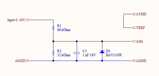
By wiring the VREF pin to AVDD or VDD (max 3.3 volt) it's possible to read a max voltage of 3.24 volt with a resolution of 10 bit (1024 samples). In this way the max sample resolution we obtain is about 3.24V/1024 ~= 3mV.
On VREF no voltage higher than 3.3 Volt can be applied. If you need to read a higher signal use a schematic like this:
Reading the A/D converter lines:
Documentation Terms of Use
The Acme Systems srl provides this Debian system development and user manual.
The origin of these doc came from the website: http://www.acmesystems.it
This work is licensed under a Creative Commons Attribution-NonCommercial-ShareAlike 3.0 Unported License.


